


We have chosen the step by step tutorial of setting up a smart home as the best learning option. In this guide you will find how our model house looks like, how rooms are labeled and what we will control in our model house. If you learn to set up a model house, it will be easy for you to adjust the number of lights and their labels so that the setting fits your real project. Let's go!
Pi-Home model house
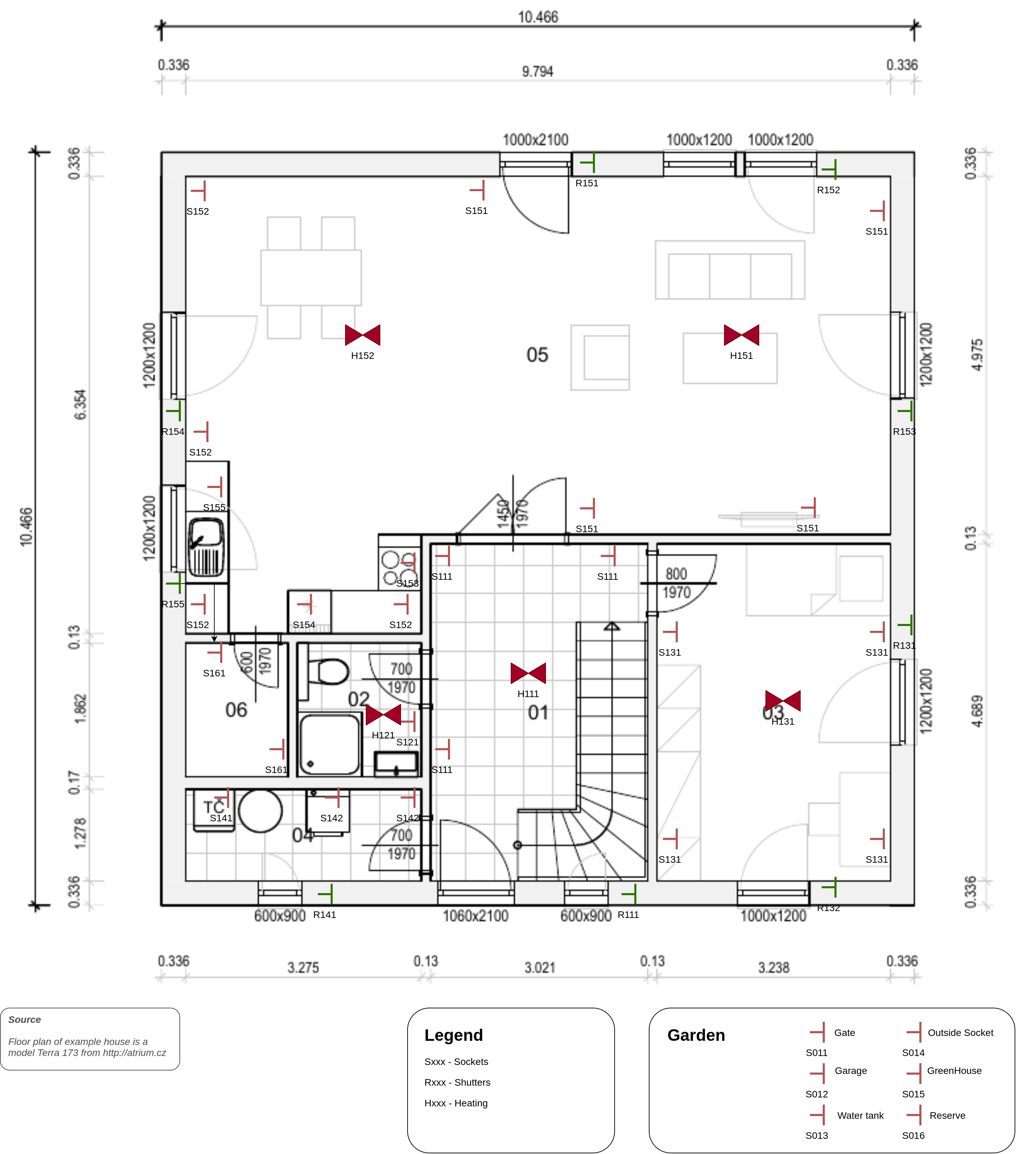
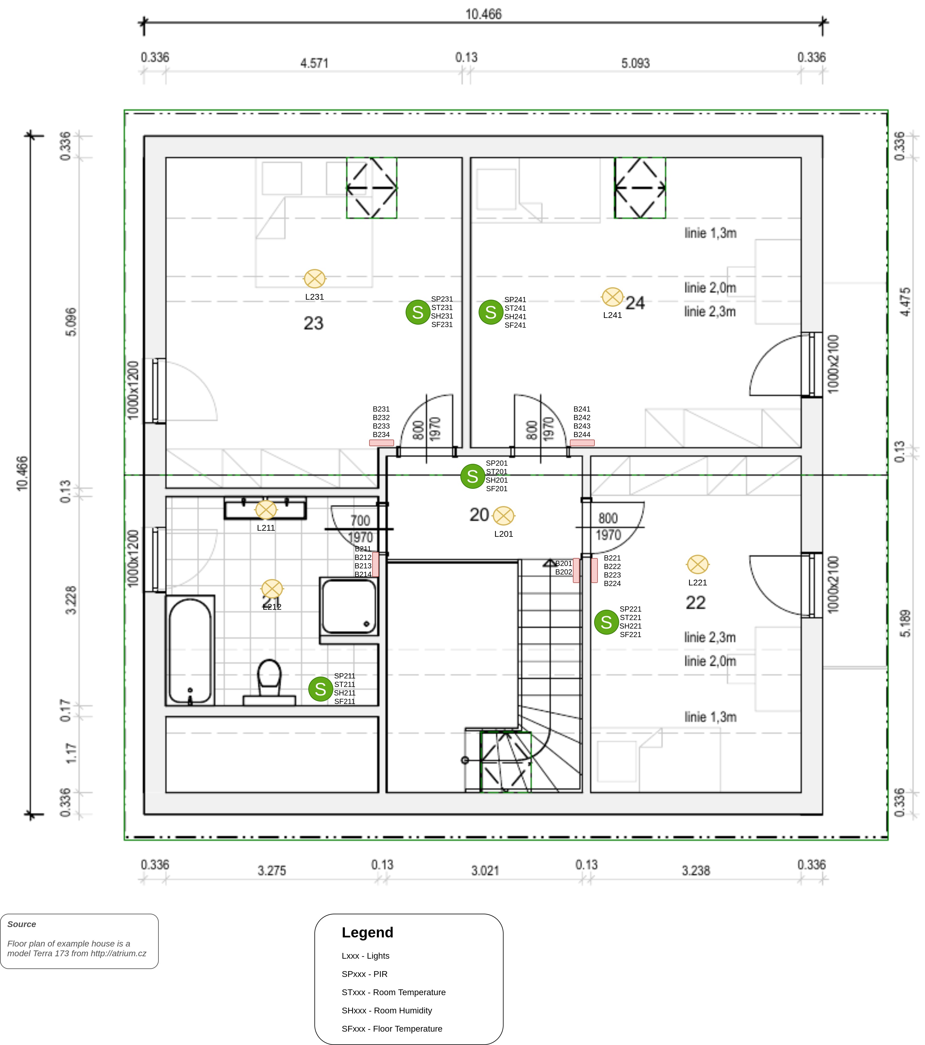
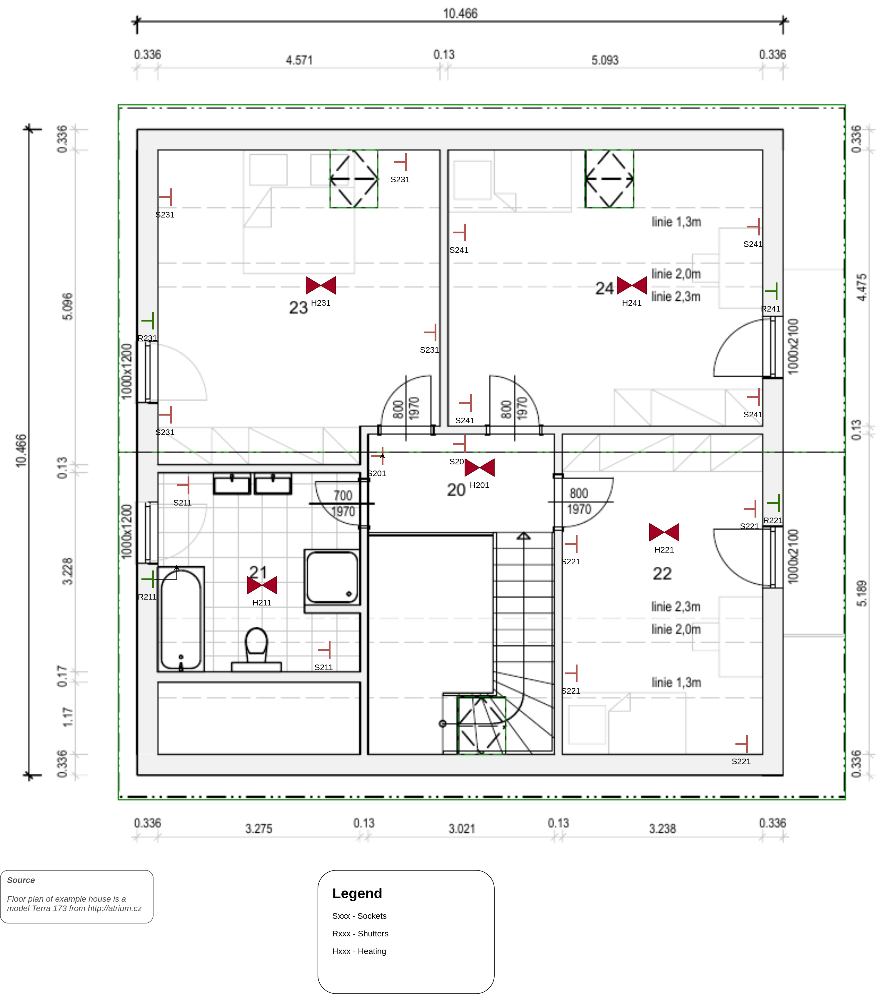
Our model house has a floor plan ~ 10 x 10 m . To avoid having to reinvent the wheel we used the finished floor plan of the real house Terra 173 by Atrium company with their permission. The ground floor rooms are coded as 1xx and the first floor as 2xx. Everything is for the purpose of the tutorial labelled in English.
The house contains the following types of controlled circuits and their coding:
| Lights Lxxx | Sockets Sxxx | Shutters/Blinds Rxxx |
| Heatings Hxxx | Butons Bxxx | PIR sensors SPxxx |
| Temperature senors STxxx | Humidity sensors SHxxx | Temperature floor sensors SFxxx |
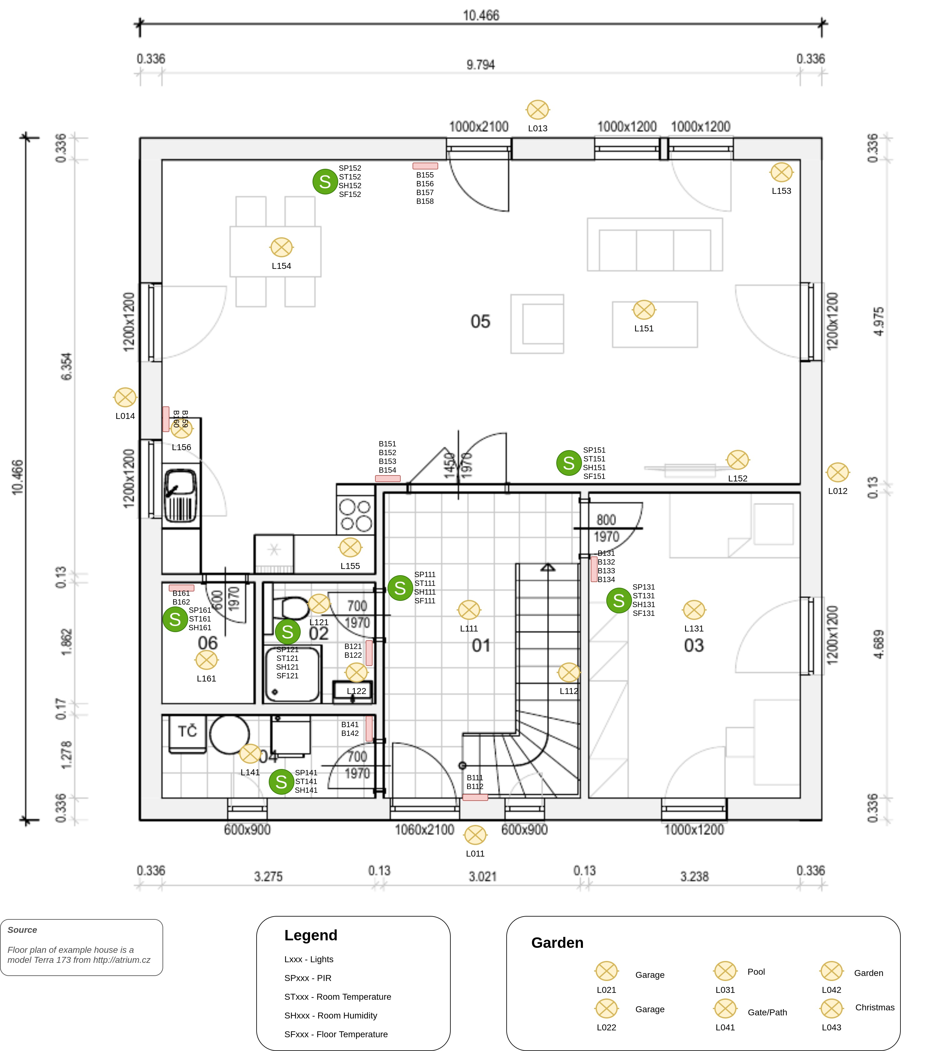
The coding you have chosen will be with you almost forever, so think about making it as versatile as possible. A well-chosen coding will give you easy orientation in modules, cables and code. It should be as short as possible, without accents or special characters.
The following table shows the codes and numbers of each type of controlled circuit/sensor:
| Lights | Sockets | Heatings | Shutters | Buttons | Sensors | ||||||
| Temp | Floor Temp | Humidity | PIR | ||||||||
| 1 | L011 | S011 | H111 | R111 | B111 | ST111 | SF111 | SH111 | SP111 | ||
| 2 | L012 | S012 | H121 | R131 | B112 | ST121 | SF121 | SH121 | SP121 | ||
| 3 | L013 | S013 | H131 | R132 | B121 | ST131 | SF131 | SH131 | SP131 | ||
| 4 | L014 | S014 | H151 | R141 | B122 | ST141 | SF151 | SH141 | SP141 | ||
| 5 | L021 | S015 | H152 | R151 | B131 | ST151 | SF152 | SH151 | SP151 | ||
| 6 | L022 | S016 | H201 | R152 | B132 | ST152 | SF201 | SH152 | SP152 | ||
| 7 | L031 | S111 | H211 | R153 | B133 | ST161 | SF211 | SH161 | SP161 | ||
| 8 | L041 | S121 | H221 | R154 | B134 | ST201 | SF221 | SH201 | SP201 | ||
| 9 | L042 | S131 | H231 | R155 | B141 | ST211 | SF231 | SH211 | SP211 | ||
| 10 | L043 | S141 | H241 | R211 | B142 | ST221 | SF241 | SH221 | SP221 | ||
| 11 | L111 | S142 | R221 | B151 | ST231 | SH231 | SP231 | ||||
| 12 | L112 | S151 | R231 | B152 | ST241 | SH241 | SP241 | ||||
| 13 | L121 | S152 | R241 | B153 | |||||||
| 14 | L122 | S153 | B154 | ||||||||
| 15 | L131 | S154 | B155 | ||||||||
| 16 | L141 | S155 | B156 | ||||||||
| 17 | L151 | S161 | B157 | ||||||||
| 18 | L152 | S201 | B158 | ||||||||
| 19 | L153 | S211 | B159 | ||||||||
| 20 | L154 | S221 | B160 | ||||||||
| 21 | L155 | S231 | B161 | ||||||||
| 22 | L156 | S241 | B162 | ||||||||
| 23 | L161 | B201 | |||||||||
| 24 | L201 | B202 | |||||||||
| 25 | L211 | B211 | |||||||||
| 26 | L212 | B212 | |||||||||
| 27 | L221 | B213 | |||||||||
| 28 | L231 | B214 | |||||||||
| 29 | L241 | B221 | |||||||||
| 30 | B222 | ||||||||||
| 31 | B223 | ||||||||||
| 32 | B224 | ||||||||||
| 33 | B231 | ||||||||||
| 34 | B232 | ||||||||||
| 35 | B233 | ||||||||||
| 36 | B234 | ||||||||||
| 37 | B241 | ||||||||||
| 38 | B242 | ||||||||||
| 39 | B243 | ||||||||||
| 40 | B244 | ||||||||||
| Sum | 29 | 22 | 10 | 13 | 40 | 12 | 10 | 12 | 12 | Total | 160 |
| Arduino1 (PA1) | Arduino2 (PA2) | Arduino3 (PA3) | Arduino4 (PA4) |
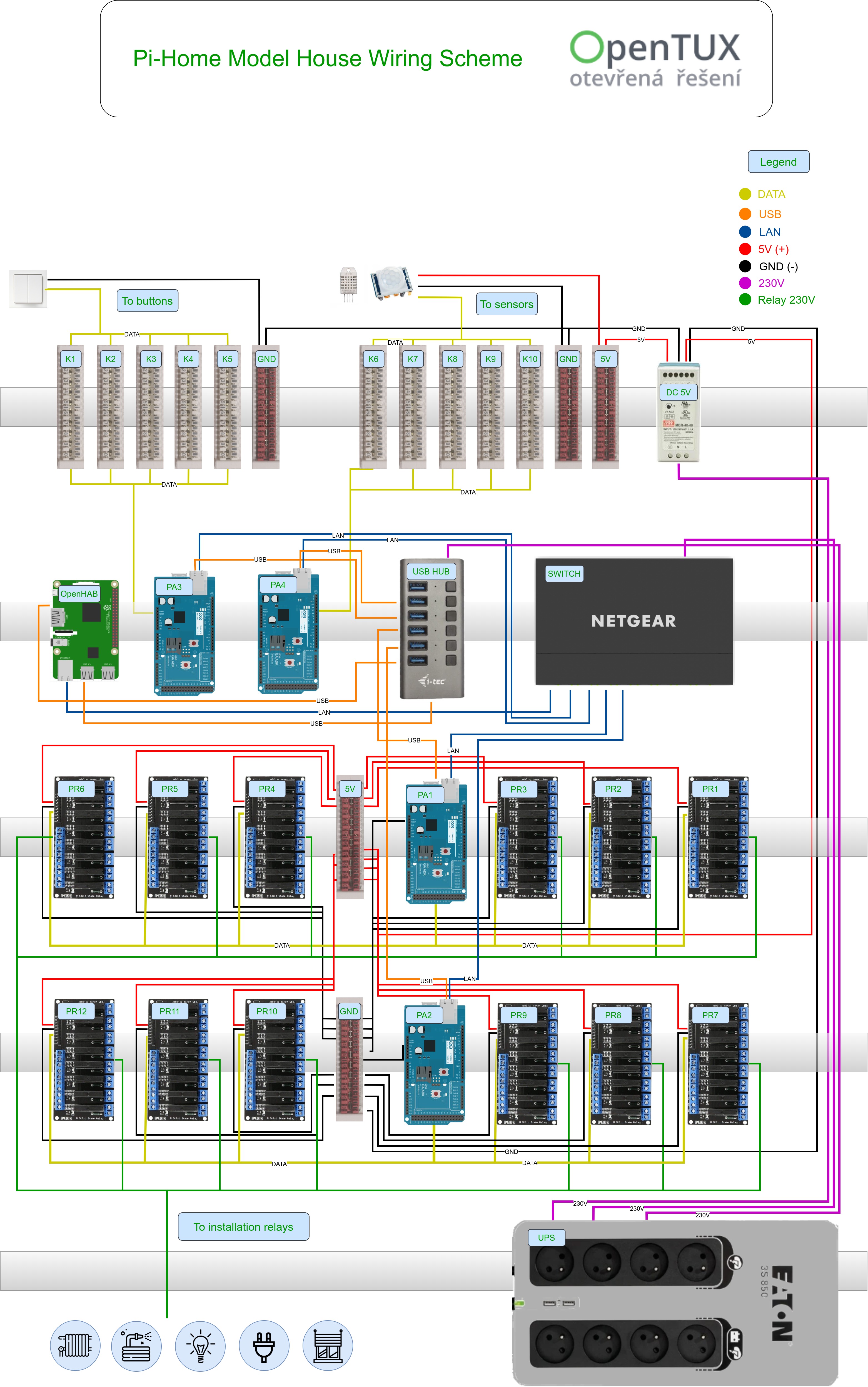
Wiring scheme
The diagram of the low-current switchboard for this model house is as follows. In this case, a separate switchboard with a size (in x w x h) of 1200x800x300 mm and 6 to 7 DIN levels with a spacing of 150mm is recommended. Cable perforated plastic U are suitable to be installed between DIN strips.
Note: The low-current part in this case does not contain an installation relay. These are located in the high-current installation and only the control cables of switching coils are pulled into the low-current switchboard.
Features
Well, what will our model house be able to do after this tutorial?
| Feature | Note |
| Control 29 lights circuits | Switch on/off of 230V circuit without dimmer, we recommend wireless devices for dimming if neccessary - Zigbee, Zwave, Shelly, etc. |
| Control 22 socket circuits | Why? We can turn off power in all circuits after we leave the house -> children's room, washing machine, iron, oven, etc..Advantage of maximum consumption logic in connection with PV panels. |
| Control 10 heating zones | Direct switching of electric heating (heating cables, electric radiators) or opening/closing of heating valves for the given zone. Logic of temperature control based on values from the room temperature sensor + possibly in combination with floor temp sensor. |
| Control 13 blinds/shutters | Direct motor control with up/down/stop through multi phase cable. Rotation function of blades (open, close). Group control. Connection to weather station. Can be extended with various rules according to time of the year, forecast, etc. |
| Control 40 buttons | Classic 230V buttons (not switches). Tested for Hager/Berker (2 and 4 buttons). Connection via UTP cable. Safe voltage 5V to ground (GND). |
| Monitor room temperature 12 x | We are using combined sensor DHT22 + PIR HC-SR501. Any Arduino compatible solution or MQTT sensors can be used as well as Z-Wave, Zigbee. |
| Monitor room humidity 12 x | We are using combined sensor DHT22 + PIR HC-SR501. Any Arduino compatible solution or MQTT sensors can be used as well as Z-Wave, Zigbee. |
| Monitor motion in room 12x | We are using combined sensor DHT22 + PIR HC-SR501. Any Arduino compatible solution or MQTT sensors can be used as well as Z-Wave, Zigbee. |
| Monitor floor temperature 10x | Solution with water-resistant sensor DS18B20 directly connected to UTP and the to Arduino pins. |
| Alarm | 12 motion sensors primarily used to control the lights (hallways, bathroom, pantry, etc.) are switched to security mode at the time of leaving the house with immediate notification (email, telegram) |
| Optional extensions: |
Add new comment